
Shaped wheel treads, a shared axle and the geometry of a curve
A train rounds a bend without a driver turning a steering wheel. Look at a conventional wheelset and the puzzle gets better: the two wheels are fixed to the same axle, so they turn together. Yet the outside rail follows a longer path than the inside rail. How can both wheels keep rolling?
The answer lies partly in a detail that is easy to miss. A railway wheel’s running surface is shaped, not simply a flat-sided cylinder. The point where the rail touches that shape can move sideways, changing the radius at which the wheel rolls.
The tread carries the load; the flange has another job
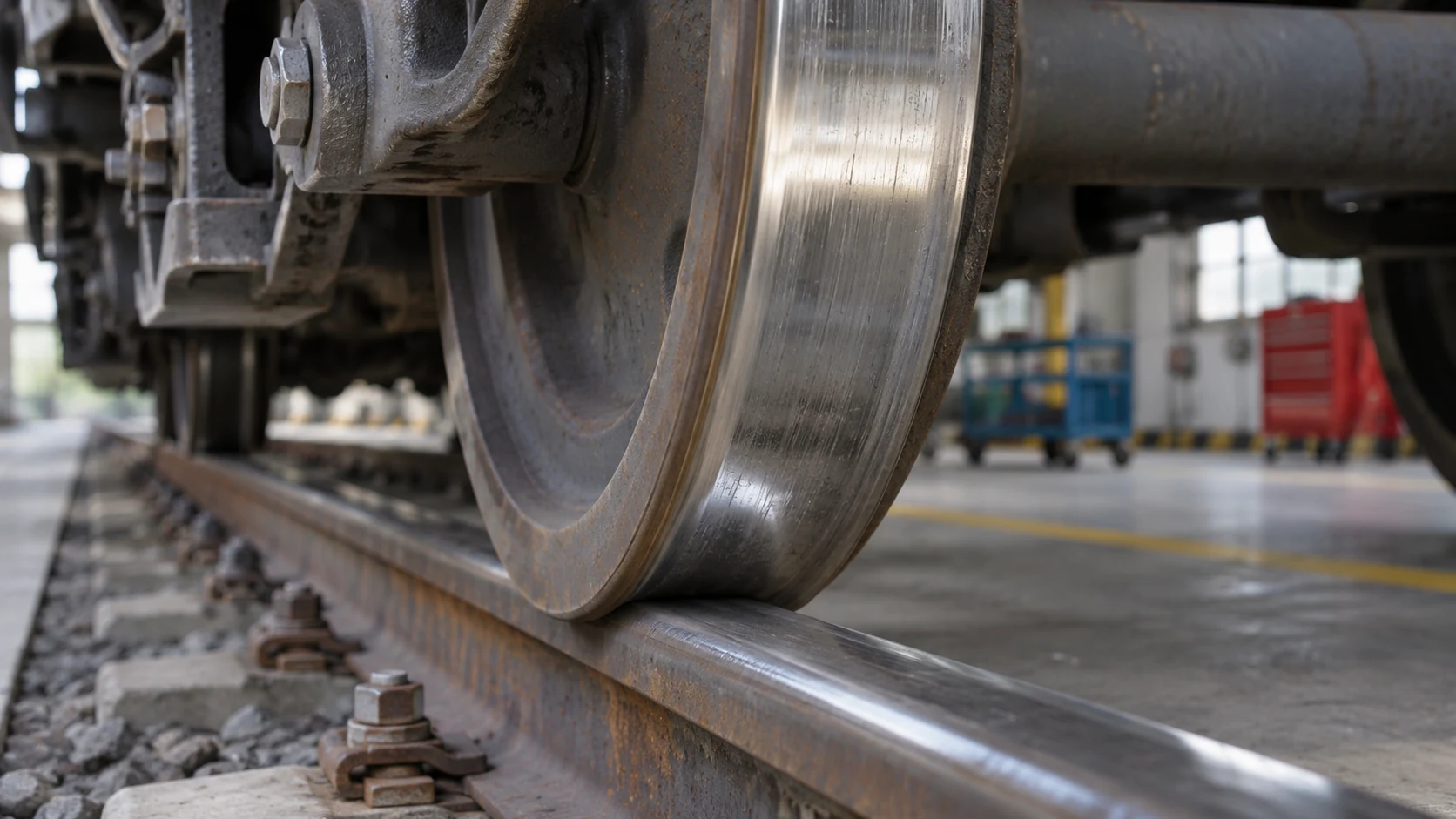
The broad running surface of a wheel is its tread. It contacts the top of the rail. The flange is the projecting rim on the wheel’s inner side, beside the railhead. In a conventional wheelset, the flange is not the main surface carrying the vehicle’s weight.
A technical account by railway engineer Piers Connor describes the interaction between the shaped wheel tread and the curved railhead, while noting that actual profiles are usually more complex than a single straight taper. The simple cone is a teaching model for a carefully designed contact geometry. [1]
That distinction matters when looking at a photograph. A flange extending beside a rail can appear to be clutching it. It is better understood as part of the system that limits and guides lateral movement, while the tread rolls on the rail’s upper surface.
Two wheels form one rotating unit
In the conventional arrangement discussed here, both wheels are firmly connected to a rigid axle. They complete the same number of turns in the same time. That is different from a road vehicle whose driven wheels can rotate at different speeds through a differential.
The Contact Patch’s engineering explanation identifies this rigid connection as central to the wheelset’s steering behaviour. A small lateral displacement puts the two wheels on different parts of their shaped treads. They can then have different effective rolling radii even though their rotation rates remain equal. [2]
“Different rolling radius” does not mean one whole wheel grows while the other shrinks. Each wheel already has a range of possible radii across its tread. The rail’s contact point selects which part is doing the rolling at that instant.
Why the outside wheel needs to travel farther
Draw two concentric arcs on paper. The outer arc is longer than the inner one for the same change in direction. A pair of rails through a curve creates that same basic distance problem for a wheelset.
For a simplified illustration, imagine the contact paths are 1.5 metres apart and the centre of the track follows a curve of radius 150 metres. The outer path has radius 150.75 metres; the inner path has radius 149.25 metres. Their lengths are in the same ratio as those radii: approximately 1.010.
In that idealized geometry, the outside wheel would need to roll about one per cent farther during the turn. If both wheels make the same number of revolutions, a matching difference in effective rolling radius can provide that distance difference. This is an illustration of the geometry, not a specification for a particular train or curve.
The thought experiment also shows why “both wheels rotate together” does not imply “both cover exactly the same distance”. Distance per revolution depends on the radius at the contact, not just on the number of revolutions.
A sideways shift changes the rolling radii
In the simplified conical model, the tread radius is larger toward the flange and smaller toward the outer edge. As a wheelset shifts toward the outside of a curve, the outer wheel can roll on a larger-radius part of its tread, while the inner wheel rolls on a smaller-radius part.
That gives the pair a way to accommodate the longer outer path without a road-style differential. It also helps explain the tendency of a displaced rolling wheelset to turn back toward a more central position on straight track. [2]
The real contact is not a perfectly rigid mathematical point. Wheel and rail deform under load, and small relative movements at the contact influence the forces. Geometry explains the central idea, but it does not eliminate the need for a vehicle-dynamics model.
| Part or property | Contribution | Useful distinction |
|---|---|---|
| Shaped tread | Changes effective rolling radius with lateral position. | A real profile is more complex than a perfect cone. |
| Rigid axle | Keeps the two wheels rotating together. | Equal rotation rate does not require equal rolling distance. |
| Flange | Provides additional lateral guidance and restraint. | It is not a hook underneath the rail. |
| Bogie and suspension | Connect the wheelsets to the body while accommodating movement. | The whole vehicle must follow the curve. |
| Track geometry | Sets the paths and contact conditions presented to the wheels. | Rails, supports and junctions form a maintained system. |
Why flanges still matter
The self-guiding description does not make flanges redundant. Tight curves, junctions and the actual forces and alignments of a vehicle can require flange contact. Nor should “flanges do not normally rub continuously” be rewritten as “a flange never touches a rail”.
Connor’s account describes flange contact and the compromises involved in negotiating curves. It also discusses bogies: supporting frames containing wheelsets, often called trucks in North American railway usage. Their movement helps a long vehicle change direction while its body remains supported. [1]
Consider a long passenger carriage. The front and rear wheel assemblies encounter different parts of a bend at the same time. Explaining only one isolated wheel cannot explain how that entire carriage is guided. The geometry of the wheelset is the starting point, with the bogie and suspension completing more of the picture.
The same geometry can produce unwanted hunting
A self-guiding wheelset does not simply find the centre once and remain motionless there. Under some conditions, side-to-side movement can develop into an unwanted oscillation known as hunting. Wheel profiles, rail profiles and the vehicle’s dynamic behaviour all influence it.
MxV Rail’s 2025 research digest describes simulations investigating the wheel-rail combinations that contribute to severe hunting. It notes the trade-off: profile coning helps wheelsets negotiate curves and maintain a suitable rolling position, but it can also be associated with instability on straight track. [3]
This is why “more taper must always steer better” is a poor conclusion. A feature that helps in one situation can create a compromise in another. Safe railway design involves the response of a moving vehicle across a range of speeds, loads and track conditions.
Equivalent conicity describes the pair of surfaces
Engineers need a way to describe the steering effect of actual wheel and rail shapes together. Equivalent conicity is one such measure. It concerns their geometric interaction, rather than a single angle measured from a new wheel in isolation.
RSSB’s research summary on determining equivalent conicity identifies wheel and rail shape as fundamental to safe, efficient operation. It connects high equivalent conicity with hunting and infrastructure damage, showing why profile management is an operating issue as well as a manufacturing decision. [4]
For a reader, the takeaway is to ask “which wheel meets which rail?” A nominal wheel drawing alone cannot specify every in-service contact condition. Both surfaces change with use, and the vehicle responds to the combination.
Rails are maintained shapes, not just steel lines
Network Rail describes track as a structure including rails, sleepers, switches and crossings. Its maintenance work includes grinding the railhead profile, maintaining support geometry and using measurement equipment to identify flaws. [5]
That work follows naturally from the guidance explanation. If contact geometry matters, wear matters. If the path of each rail matters, the supports holding those rails in position matter. The visible wheel and the visible strip of steel are interfaces within a larger engineered system.
There is a parallel with ball bearings: the small region where surfaces meet can determine the behaviour of a much larger machine. The relevant question is how forces pass through that contact, not just how impressive the surrounding structure looks.
Questions readers ask
Do railway wheels have a steering wheel?
Conventional trains do not use road-style steering. Wheel-rail geometry and contact forces guide the wheelsets, while the track determines the route.
Are train wheels perfect cones?
No. A shallow cone is a helpful introductory model, but real tread profiles are shaped curves designed for the intended wheel-rail system.
Why do the two wheels not need to spin at different speeds?
Their effective rolling radii can differ. That lets a rigidly connected pair cover different distances per revolution.
Do the flanges always touch?
No. Continuous flange rubbing is not the basic self-guiding mechanism, although flange contact can be important in particular operating conditions.
Does this describe every rail vehicle?
No. This explanation concerns conventional rigid-axle wheelsets. Other arrangements, including independently rotating wheels, require additional explanations.
The steering is hidden in the contact
The surprising feature is not that a train has no steering wheel. It is that a small lateral change at two carefully shaped contacts can alter how far each wheel rolls. Put that geometry together with the axle, bogie, suspension and maintained track, and the bend becomes an engineering problem the whole system is built to solve.
Continue exploring
Sources and further reading
- Piers Connor, Railway Technical Website — Wheels and Bogies
- The Contact Patch — R.1610 The wheelset
- MxV Rail (2025), Technology Digest TD24-022 — Wheel-Rail Interaction Affecting Hunting Stability
- RSSB — Improving management of the wheel/rail interface: A simple method to determine equivalent conicity
- Network Rail — Track and its maintenance
Keep exploring.
One remarkable idea at a time—nature, science, history and beyond.
Last updated November 6, 2026.

Barnakle Editorial Team
Barnakle Editorial Team is the collective byline used for Barnakle’s editorial articles. The contributor profile explains the team identity and links to the publication’s editorial policies.
More from the editorial team →