
The short answer
A transformer changes voltage by linking coils through a changing magnetic field. An alternating voltage applied to the primary winding produces changing magnetic flux. That flux links the secondary winding and induces another voltage. In an ideal transformer, the voltage ratio follows the ratio of turns in the two windings. Raising voltage goes with lower current for the same transferred power; the transformer does not create extra energy. [1][2]
A transformer can look unimpressive: copper wire wrapped around a heavy core, sometimes hidden inside a tank or an electronic power supply. Yet versions of this device connect enormous electricity networks to everyday appliances. Understanding it starts with a distinction between moving charges along a wire and transferring energy through a magnetic field.
Two circuits share a magnetic link
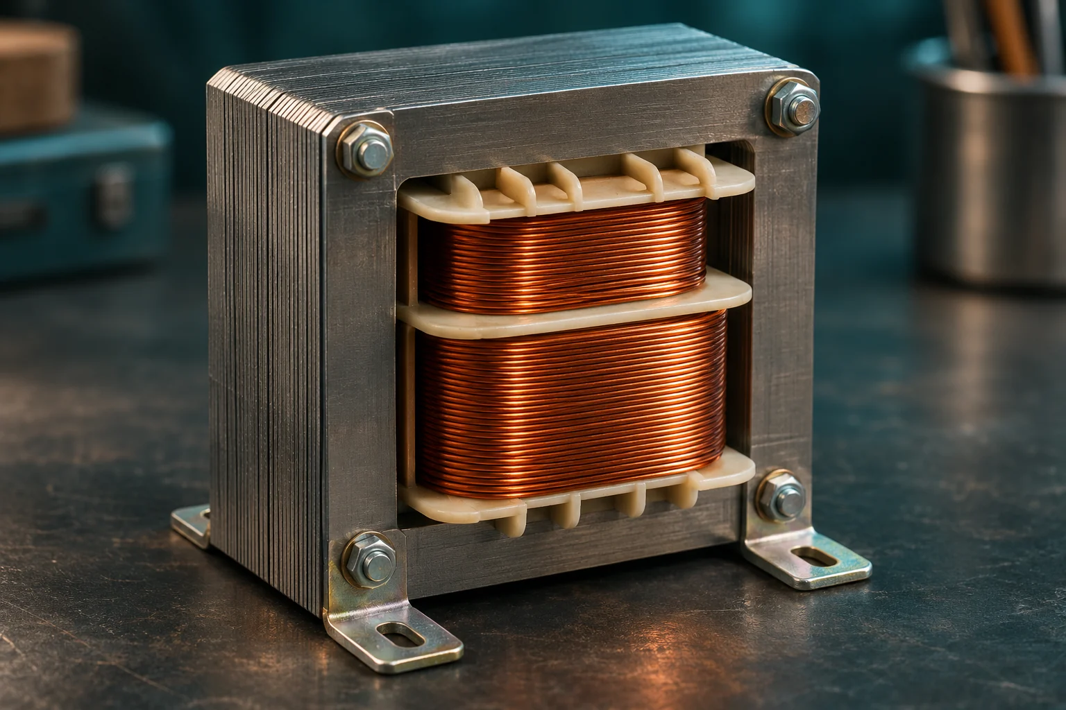
The primary is the winding connected to the incoming source. The secondary supplies the outgoing circuit. In a conventional two-winding transformer, the copper conductors are electrically insulated from each other. Their connection is magnetic, rather than a wire that simply joins one circuit to the next. [2]
Changing current in the primary contributes to a changing magnetic field. A magnetically permeable core helps guide the flux so that much of it links both windings. Faraday’s law describes the voltage induced when the magnetic flux through a loop changes. A secondary winding contains many loops, so their induced voltages add.
An open secondary can have a voltage across its terminals even though it supplies essentially no load current. Closing a suitable load circuit allows current to flow. Voltage and current are related, but they are not interchangeable descriptions of what a circuit is doing.
Why the number of turns matters
Imagine an ideal transformer whose primary contains 400 turns and whose secondary contains 100. If the primary receives 120 volts AC, the ideal secondary voltage is 30 volts AC. The secondary has one-quarter as many turns, so it develops one-quarter of the voltage. This is an illustrative calculation, not instructions for building a mains-powered device.
The relationship is often written as Vsecondary / Vprimary = Nsecondary / Nprimary. Here N means the number of turns. More secondary turns produce a step-up transformer; fewer produce a step-down transformer. A one-to-one transformer can transfer energy without deliberately changing the voltage. [3]
This rule assumes that both windings link the same changing flux and that losses are negligible. It is a useful starting point for understanding a real component, rather than a promise that every measured output will equal an exact arithmetic result.
Higher voltage does not mean free power
Electrical power in the simplest ideal example is voltage multiplied by current. If a transformer transfers 120 watts and delivers 30 volts to a suitable load, its output current is 4 amperes. An ideal 120-volt primary would draw 1 ampere for that transfer. Real input power must also cover losses.
The lower-voltage winding therefore needs to carry more current for the same power. That affects wire thickness and thermal design. Adding secondary turns to obtain a higher voltage cannot simultaneously produce unlimited current. The supply, windings, core and cooling arrangement all impose limits. [4]
The example also explains why voltage alone says little about a transformer’s size. Two units with the same nominal output voltage may have very different power ratings. One might serve a tiny electronic load; another may need to supply equipment drawing much more current.
Why electricity travels at high voltage
Long transmission lines have resistance. Current through that resistance produces heating losses described by I squared times R. For a simplified fixed-power comparison, increasing transmission voltage allows current to decrease. Halving current reduces that resistive heating to one-quarter, if resistance stays the same. [3]
That is why an electricity system can raise voltage near generation, carry power over long distances, then reduce voltage through several stages near its users. The wires do not become lossless. The system changes operating conditions so that less of the transmitted energy becomes unwanted heat. [1]
A real grid must also account for insulation, clearances, alternating-current behaviour, equipment ratings and operating requirements. Higher voltage is useful within an engineered system; simply increasing it without addressing those other constraints is not an improvement.
Why ordinary transformers need a changing input
A steady magnetic field does not continually induce voltage in a stationary secondary winding. Conventional power transformers therefore operate with changing excitation, commonly alternating current. Connecting a winding to an unsuitable steady DC source is not equivalent to operating it at its rated AC conditions. [5]
There can be a transient when a circuit is switched, but that is different from continuous normal operation. With sustained DC, a conventional winding may draw excessive current because the expected inductive behaviour is absent. Its wire resistance alone may not safely limit the current.
This does not mean electronics can never transform energy from a battery. A switching converter first changes the electrical waveform. Many such designs use a transformer at a much higher frequency, followed by further circuitry. The complete power supply does more than its transformer alone.
What the core does—and what it loses
The core provides a useful path for magnetic flux. Many power-frequency transformers use stacks of thin insulated steel laminations. Dividing the conductive core into sheets helps limit circulating eddy currents and the heating they cause. Other designs use materials suited to higher frequencies. [5]
Real transformers also lose energy through winding resistance and magnetic hysteresis, among other effects. Some flux does not link both windings perfectly. These details help explain why efficiency is below 100 percent and why the output can change when a load is connected.
A warm enclosure is therefore not evidence that a transformer has invented heat from nowhere. Some of its incoming electrical energy is being dissipated. Equipment designers manage those losses through materials, construction, operating frequency and cooling.
Why some transformers hum
Magnetic forces and tiny changes in core dimensions can create vibration. The familiar low hum is a mechanical response to electrical and magnetic operation, not the intended energy-transfer mechanism. The device does not need a rotating shaft to work. [4]
A useful comparison is an electric motor. Both devices involve magnetic fields and coils, but a motor deliberately produces mechanical motion. A transformer primarily transfers electrical energy between circuits. Similar ingredients do not make them the same machine.
Is a transformer the same as a charger?
Usually not. A charger or adapter may contain a transformer together with switches, rectifiers, filters and control circuits. A transformer by itself generally does not turn alternating current into regulated direct current. Rectification and regulation are separate jobs. [6]
Nor does every voltage-changing circuit contain a transformer. Different converter designs use different components. Saying that an adapter changes voltage identifies a task, but not the entire method inside its housing.
Common questions
### Does a transformer use electricity with nothing plugged into its output? A real energized transformer can consume some power even with an unloaded secondary because its core and other components have losses. It may also draw magnetizing current. No-load consumption and full-load efficiency describe different operating conditions.
Are the two windings always electrically isolated?
No. A conventional isolated two-winding transformer is a useful teaching model, but an autotransformer uses a shared winding connection. The word transformer alone does not guarantee electrical isolation or make a circuit safe to touch.
Can a step-down transformer supply any appliance with the right voltage?
The voltage rating is only part of the requirement. Frequency, current capacity, waveform, insulation and the appliance’s own requirements matter. A component’s matching voltage label does not establish compatibility.
What is the main idea to remember?
A transformer uses changing magnetic flux to transfer electrical energy. Its turns ratio relates the voltages, while energy conservation relates the available currents. That combination makes it useful for both small circuits and large power networks.
Keep exploring
Sources and further reading
- U.S. Energy Information Administration — Batteries, circuits and transformers
- OpenStax — Motors, generators and transformers
- Monash University — Transformers and transmission of electricity
- University of Waterloo Engineering Ideas Clinic — Transformers
- U.S. Department of Energy — Electrical Science, Volume 4: Transformers (handbook PDF)
- University of Calgary Energy Education — Transformer
Reference review: November 12, 2026.
Keep exploring.
One remarkable idea at a time—nature, science, history and beyond.
Last updated November 13, 2026.

Barnakle Editorial Team
Barnakle Editorial Team is the collective byline used for Barnakle’s editorial articles. The contributor profile explains the team identity and links to the publication’s editorial policies.
More from the editorial team →