
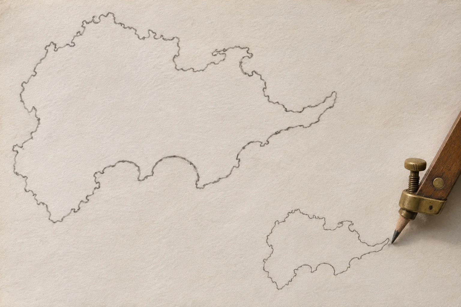
A bay on a hand-drawn coast is four centimetres wide. On the smaller map beside it, a pencil traces the same bay two centimetres across. The person moving the pencil hasn’t measured either distance. In fact, the hand is on a different part of the instrument, guiding a blunt point around the original shoreline. Several hinged bars take care of the arithmetic as the point moves. This is a drawing pantograph.[1, 2]
A pantograph copies an outline using a fixed pivot, a tracer and a writing point. Its bars form an adjustable parallelogram. At a chosen setting, the linkage holds the pencil at a fixed fraction or multiple of the tracer’s distance from the pivot, along the same straight line. As the tracer rounds a headland, the direction of that line keeps changing. The distance ratio stays the same. Hundreds of positions that would be tedious to plot by hand arrive in the right place as one continuous pencil stroke.[1, 2]
The one point that stays put
Mount the pivot on a drawing board and imagine tying a piece of thread from it to the tracer. In a common reduction arrangement, the pencil lies somewhere along that imaginary thread. At half scale it sits halfway out. If the tracer is twenty centimetres from the pivot, the pencil is ten centimetres away. If the tracer moves out to thirty, the pencil reaches fifteen. So far this sounds like a device for halving distances along a ruler. The interesting part happens when the hand turns sideways.[1, 2]
Keep the tracer at the same distance from the pivot and swing it through a small arc. The pencil sweeps through the same angle on an arc with half the radius. Its curved journey is half as long. A real shoreline combines motion toward the pivot, motion away from it and motion around it, all in quick succession. The linkage handles these components together. It has no need to recognize a bay, detect a corner or know when the drawing is finished.[1, 2]
Why four moving bars can preserve an angle
A parallelogram can lean from one side to the other without losing the parallel relation between opposite sides. The pantograph uses that freedom. Its joints let the linkage open and close as the operator traces, while the parallel bars establish triangles with matching angles. Those triangles are similar, which means that their corresponding sides maintain the same proportion. With the joints and tool points in the intended positions, that proportion connects the pivot, the tracer and the pencil.[1, 2]
Here’s a way to test the claim on paper. Mark two corners of a rectangle, one above the other, on a sheet. Locate the halfway point on a straight line from the pivot to each corner. Join the two halfway points. The new edge runs parallel to the original edge and has half its length. Do the same for the remaining corners and the small rectangle has the same proportions as the large one. The pantograph performs that construction at every intermediate position, including points on shapes with no convenient corners.[2]
A mapmaker's scale has consequences
Suppose the source map represents one kilometre with two centimetres on the page. At half scale, a kilometre now takes up one centimetre. The little island still has the same longitude and latitude in the world. What has changed is the amount of paper it occupies. If the original encloses a square four centimetres on a side, the copy encloses a square two centimetres on a side. Its area has fallen from sixteen square centimetres to four even though the operator selected a one-half setting.[1, 2]
A drawn scale bar will shrink along with the island if it is traced at the same setting. A written statement such as “two centimetres to one kilometre” needs editing. So do labels if the reduced lettering would be too small to read. In another respect the pencil has a mind of its own. Its line width depends on its tip, the pressure and the paper. A half-size coastline drawn with the same pencil can look heavier relative to its tiny inlets. Geometry reproduces the path down the middle of the stroke.[1, 2, 3]
What the old instruments looked like
The Institution of Mechanical Engineers holds a brass pantograph made by Elliot Brothers around 1850. London’s Science Museum Group also records a late eighteenth-century instrument by Wilkinson. A later example, made by William Ford Stanley in London in 1876, survives on a board with a drawing and a separate stand. Its longer arm measures two feet. Seen beside paper rather than in a diagram, that length gives a better sense of the sweep needed on a draughtsperson’s desk.[3, 4, 5]
A real instrument introduces practical decisions that a proof on paper can ignore. The operator needs room for the linkage to swing through its full range. The original, the blank sheet and the fixed support must stay in the same relative positions until the outline is complete. If the sheet shifts while the tracer is making its way inland around a bay, perfect joints will faithfully put the rest of the drawing in the wrong place. A mark at a known starting point offers a straightforward check when the outline closes.[1, 3, 5]
What happens to a mistake?
Imagine that the hand wanders one millimetre away from the coast. On an ideal half-size copy, that sideways detour appears as half a millimetre. Reverse the arrangement to produce an enlargement at twice the size and a one-millimetre detour becomes two. Play in a joint or a pencil that leans can introduce additional error. Enlarging a faint plan makes its details easier to see, but there is no mechanism in the bars that can supply information the original draughtsperson left out.[1, 2, 3]
Return the tracer to the mouth of the bay and the pencil returns to its partner point. Nothing in the instrument stores the coastline. When it is lifted off the board, the only lasting record is the line the pencil has left behind. That is the appeal of watching a pantograph work. A geometrical relationship you could demonstrate with triangles becomes a movement your hand can feel, and a second drawing appears beside the first.[1, 2]
Related reading
- How Do Japanese Woodblock Printers Line Up Different Colours?
- How Do 3D Printers Turn a Digital File into an Object?
Sources
- Museo Galileo — The drawing pantograph
- Alexander Bogomolny, Cut-the-Knot — Pantograph geometry and similar triangles
- Institution of Mechanical Engineers — A nineteenth-century drawing pantograph
- Science Museum Group — A late eighteenth-century pantograph by Wilkinson
- Science Museum Group — William Ford Stanley’s board-mounted instrument
Keep exploring.
One remarkable idea at a time—nature, science, history and beyond.
Last updated November 21, 2026.

Barnakle Editorial Team
Barnakle Editorial Team is the collective byline used for Barnakle’s editorial articles. The contributor profile explains the team identity and links to the publication’s editorial policies.
More from the editorial team →