
A digital model becomes a sequence of controlled material transformations
A 3D printer does not understand “make a useful bracket” in the way a person does. It receives a description of a shape and a sequence of operations, then controls where material is placed, joined or solidified. A useful object emerges only when those digital instructions are compatible with the physical process.
The familiar desktop machine drawing lines of warm plastic is one member of a larger family. Following that example from model to finished part gives a concrete explanation, while comparing it with resin and powder processes shows why “3D printing” is a category rather than one universal mechanism.
Follow the mechanism
- A model defines the intended geometry.
- A slicer prepares a process-specific layer plan.
- The machine places, joins or cures selected material.
- Finishing and checks turn the build into a usable part.
Start with a shape that can be manufactured
The process begins with a digital model. It might be designed from measurements, generated in computer-aided design software, or derived from a scan and then prepared for manufacture. The model describes geometry; it does not automatically supply every printing instruction.
A screen can display surfaces that are too thin, disconnected or unsupported to manufacture as intended. A digital gap may be smaller than the machine can reproduce. A decorative shape may have no useful way to bear a load. Before printing, someone must decide which dimensions and functions matter.
Imagine designing a small nameplate with raised letters. The outline, thickness and letter height are design choices. Whether the letters can be distinguished with the selected process is a manufacturing question. Having a valid file and having a suitable design are related achievements, but they are not the same one.
Sources: [1]
The slicer translates geometry into a plan
For common layer-based processes, software divides the model into a sequence of cross-sections. It then plans operations for each layer using settings appropriate to the printer and material. In filament printing, those operations include paths for exterior walls, internal material and any temporary supports.
The output is more specific than a stack of pictures. It has to tell a machine how to move and when to perform process actions. A model and a prepared machine file are therefore different stages. The same model can generate different instructions when orientation, material or settings change.
Slicing is also a useful review opportunity. A preview can expose a floating feature, an unexpectedly hollow region or a missing small detail before material is consumed. Inspecting the plan does not guarantee a good print, but it can reveal problems that a smooth shaded model view hides.
What a filament printer physically does
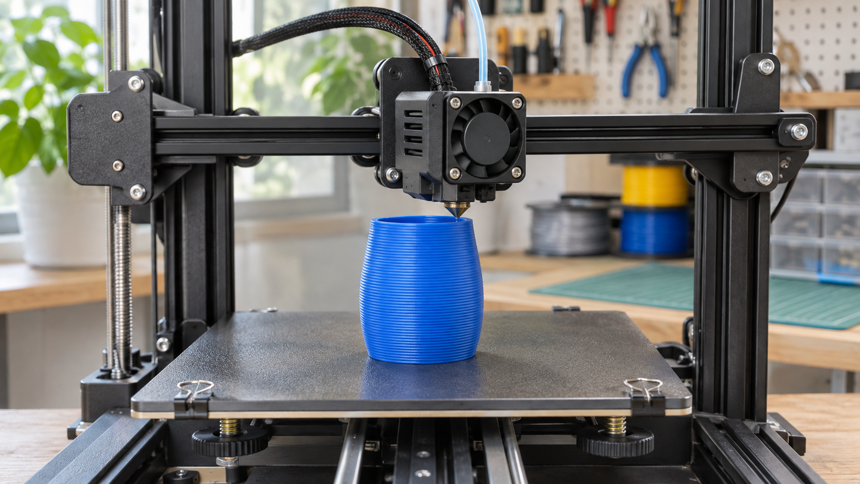
In fused-filament fabrication, a drive feeds thermoplastic filament toward a heated region. The softened material passes through a nozzle and is placed along a controlled path. As it cools, deposited material holds its shape and joins the developing structure.
The moving parts vary between printer designs. One machine moves its build platform in a particular direction while another moves the toolhead. The useful mechanism is coordinated relative motion: the nozzle must arrive at the right place while an appropriate amount of material is delivered.
A line that is placed too high, too low or without adequate support may not behave as the digital plan suggests. Temperature, flow, motion and the state of the previous material all interact. The printer is executing a manufacturing process, not merely sketching an outline in the air.
Sources: [2]
A layer is not the whole resolution story
Layer height controls the vertical spacing of successive slices. A smaller height can make a sloping surface appear less stepped, but it does not automatically improve every detail in the horizontal plane. Nozzle geometry, line placement, material behaviour and motion also matter.
For an invented example, a 100-millimetre-tall object divided into uniform 0.20-millimetre layers has 500 layers. Dividing the same height into 0.10-millimetre layers gives 1,000. That arithmetic describes layer count; it is not an exact prediction of print time or strength.
Some operations happen once per layer, some depend on path length, and some depend on acceleration or processing limits. Consequently, twice the layers need not mean precisely twice the total time. Nor can a fine layer setting rescue a feature whose width is incompatible with the chosen nozzle and process.
Sources: [3]
Walls and infill have different jobs
A filament-printed object need not be a completely solid block. Its exterior walls define much of the shape, while the interior can contain a planned pattern called infill. Top and bottom surfaces can be treated differently from the material inside.
A high infill percentage is not a universal synonym for a strong part. Wall thickness, orientation, material, bonding between layers and the direction of loading all affect performance. A setting is meaningful only in relation to the job the object must do.
Consider a hollow display model and a small mounting component. They might share an outer shape while needing very different internal structures and evidence of fitness for use. The slicer can change material placement, but selecting a denser pattern does not certify the result for a safety-critical role.
Sources: [3]
Why overhangs may need temporary support
Each new region has to be formed in relation to what is already present. A feature extending into open space may need temporary support, a different orientation, or a different manufacturing approach. The exact limit depends on geometry, material and process rather than one angle that applies everywhere.
A helpful imagined example is a small letter-shaped object. A broad horizontal stroke placed over empty space presents a different challenge from a gently changing slope with support beneath each new line. Rotating the model changes which features face that problem.
Supports are part of the manufacturing plan, not part of every intended finished object. Removing them can leave marks and may require access that a complex enclosed cavity does not provide. Designing for printing therefore includes thinking about how the temporary structure will be removed, not merely whether software can generate it.
| Process family | What forms the part | An important distinction |
|---|---|---|
| Material extrusion | Material is delivered along a controlled path. | A common desktop version uses thermoplastic filament. |
| Vat photopolymerization | Light causes selected resin regions to solidify. | The process is curing a liquid, not melting filament through a nozzle. |
| Powder bed fusion | Energy joins selected regions in successive powder layers. | Powder handling, thermal conditions and finishing are part of the process. |
Resin printing changes the material mechanism
In vat photopolymerization, selected regions of a light-sensitive resin are cured to form the object. The machine coordinates exposure with the movement and preparation needed for successive layers. Different systems deliver the light in different ways.
The central distinction is chemical solidification under controlled exposure rather than simply cooling a line of molten plastic. That changes the equipment, material handling, supports and post-processing. A resin print may need washing and further curing according to its process instructions.
This is why an explanation limited to a hot nozzle cannot account for all 3D printing. Both approaches can follow digital geometry layer by layer while relying on different physical transformations. Their files may begin with similar models, but their operating instructions are not interchangeable.
Sources: [2]
Powder processes expand the family further
Powder bed fusion spreads material in layers and uses an energy source to join selected regions. Depending on the system, the material and energy source differ. The unused material, build environment and thermal history are important parts of the manufacturing problem.
Other additive processes can deposit material while directing energy at it, jet a binding material into powder, or place droplets that are subsequently solidified. The shared idea is building material into the desired geometry, not a single method for making every bond.
NIST’s technology overview is useful here because it names several process families separately. That keeps a general explanation from turning a feature of one desktop printer into a claim about metal, polymer and ceramic manufacturing as a whole.
Sources: [2]
The printed shape still needs to become a finished part
Removing an object from the machine is not always the final manufacturing step. Supports may need removal; a resin process may require cleaning and additional curing; a metal part may need further processing and inspection. Finishing depends on the technology and intended use.
Dimensions also need checking. A model specifies an intended geometry, while a real process introduces material and machine effects. For a decorative object, a small discrepancy may be acceptable. For mating components, it may determine whether the parts fit at all.
The useful distinction is between “the machine produced an object” and “the object meets its requirements”. Additive manufacturing does not remove the need to measure, test and validate a design. It gives designers another way to create geometry, including shapes that can be awkward with other processes.
Sources: [1]
Why print orientation matters
A part can be turned before slicing, changing its contact with the build platform, its supports, the surfaces facing different directions and the sequence of deposition. In a layer-built object, orientation can also change how interfaces between layers relate to an applied load.
Imagine a thin hook built lying flat versus standing upright. The outline may look similar in the final render, but the manufacturing paths and the way layers are stacked are different. That is a design comparison, not a claim that one orientation is always stronger.
A responsible choice begins with the part’s function and the process being used. A preview helps assess the geometry; a test or validated process is needed when performance matters. A general internet explanation cannot assign a safe load rating to an untested print.
Treat the process environment as part of the machine
Printers can involve hot parts, moving mechanisms, uncured resins, powders or airborne emissions, depending on the process. The hazards are not identical across technologies. A pleasant-looking desktop enclosure is not itself proof that every material can be used anywhere.
NIOSH’s guidance for schools, libraries and makerspaces addresses printer emissions and exposure controls. Follow the printer and material instructions and the controls appropriate to the workspace. This article explains the manufacturing sequence; it is not a substitute for a material-specific operating or safety procedure.
Sources: [4]
Questions readers ask
Does a printer start with a photograph?
Some workflows can use images or scans to help build a model, but the printer still needs suitable geometry and process instructions. An ordinary photograph is not automatically a ready-to-print solid object.
Why are there visible lines?
Layer construction can leave a stepped texture, especially on sloping surfaces. Layer height is one influence; material and process settings also affect the result.
Is every printed object hollow?
No. The internal structure is a design and processing choice. Many filament workflows use exterior walls with planned infill, while other requirements call for different structures.
Is a resin printer simply a more precise filament printer?
It uses a different solidification process. Comparing them requires looking at material properties, geometry, finishing, working conditions and the intended application, not one resolution number.
Does 3D printing eliminate waste?
No. Supports, failed builds, finishing and material handling can create waste. Material efficiency depends on the complete process and the alternative being compared.
A file becomes an object through controlled material change
The essential sequence is model, manufacturing plan, controlled build and finishing or verification. The printer turns digital instructions into physical changes, whether that means depositing a line, curing resin or joining powder.
The most useful question is not simply whether a shape can appear on a screen. It is how each region will be supported, formed and checked in the real world. That is where 3D printing becomes manufacturing rather than a visual trick.
Continue exploring
Sources and further reading
Keep exploring.
One remarkable idea at a time—nature, science, history and beyond.
Last updated November 6, 2026.

Barnakle Editorial Team
Barnakle Editorial Team is the collective byline used for Barnakle’s editorial articles. The contributor profile explains the team identity and links to the publication’s editorial policies.
More from the editorial team →