
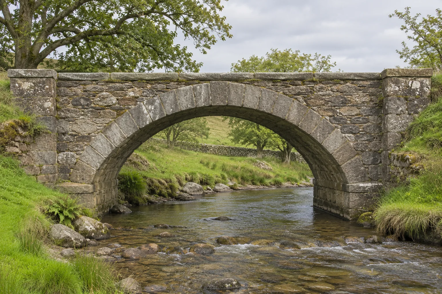
Stand beside a stone arch bridge and look through the opening from one bank to the other. There is no pillar under the middle, yet the stones overhead carry their own weight and some of the load from the roadway. Their curved arrangement lets neighbouring blocks press against one another. Those contact forces carry the load around the opening to supports on either side. At the ends, the supports must resist an outward push as well as the weight coming down. An arch and its abutments make sense as one structure. [1, 2]
Follow one block around the curve
The ring of stones visible around an arch opening is a good place to start. Many traditional arches use wedge-shaped blocks called voussoirs, or blocks set with joints that radiate around the curve. Pick one close to the top. If you pictured it in isolation, gravity would pull it down. In the completed ring, the stones against its sloping faces press back. Components of those forces can support it while the load continues through each adjoining block. [1, 2]
At the crown of a symmetrical arch carrying a symmetrical load, the direction of compression can be close to horizontal. Nearer the springing, where the arch rises from its support, the direction is more steeply inclined. That gradual change matters. If every force between successive blocks acted along the same horizontal line, the chain of contact forces would have no way to account for the increasing weight above its lower portions. The changing slope lets the ring carry weight past open air. [2]
Masonry is generally well suited to compression. It has much less dependable capacity to carry tension across the joints between separate pieces. A flat span made of loose blocks presents an immediate difficulty because bending tends to pull one side of the span apart. Curving the masonry offers a route for the load along which the pieces can stay pressed together. How well that route fits within the available thickness is more important than how impressive an individual block looks. [1, 2]
What the keystone actually does
A conspicuous block at the crown is often called the keystone. Imagine watching construction before that last gap has been closed. Sections of the ring have been built up from the two ends, but the masons still need temporary support for blocks over the opening. Traditional timber centering provides the curved support on which the arch is assembled. Once the ring is complete and ready to carry its load, the temporary support can be taken away. [1, 3]
Look again at the completed span. The crown block bears against its neighbours, and they bear against theirs. The keystone is an especially visible link in that sequence, yet pressure also crosses the quieter-looking joints halfway down each side. A decorative projecting face can make the centre stone look far more important than an otherwise similar block beside it. You cannot infer the force at a joint simply by comparing which stone projects farthest over the water.
Why the abutments have to hold their ground
Follow the lower end of the curve to the bank. Its final push has both downward and outward components. The mass and configuration of the abutment and the ground supporting it provide the corresponding reactions. A drawing cropped just at the ends of the visible arch misses part of the explanation for how the middle stays up. The forces have to reach the ground somewhere, even if the abutments blend so well into the riverbanks that they barely look like separate structures. [1, 2]
At an interior pier between neighbouring spans, one arch may push from the left and another from the right. Under similar loading their horizontal effects can partly balance. An end abutment lacks a matching span beyond it. Even an interior pier must deal with differences between its two sides when loads or spans differ. This is why the repeated arches in a long bridge should be read as an interacting series. Each transmits forces to supports that may also serve its neighbour. [1, 2]
An upside-down chain gives a clue
There is a simple geometric analogy behind one method engineers use to study arches. A freely hanging chain takes a shape in which it can carry its load through tension. Imagine making that shape rigid and turning it upside down. For the corresponding load arrangement, the inverted shape suggests a route that a compressive force could follow. The analogy describes equilibrium for a particular distribution of weight. Real arches have thickness, and the fill, roadway and traffic can distribute weight very differently from a bare chain. [2]
Engineers call such a route a line of thrust. It is a way of representing the combined contact force across successive sections of the masonry. There is no stripe on the bridge marking it. Under the usual idealized masonry assumptions, a compressive thrust line that fits within the masonry is evidence of a possible equilibrium for the chosen loading. Another loading pattern can shift the route. Judging a real bridge also requires information about materials, joints, foundations and condition that its silhouette cannot supply. [1, 2]
What the view from the river leaves out
A stone road bridge usually contains more material than the neatly outlined wedge stones visible from its side. Above the arch barrel there may be fill contained by side walls, with the road surface at the top. A vehicle passing over one point loads that larger assembly. Some force can spread through the fill before reaching the arch. The roadway can consequently look almost level even where the opening beneath it is strongly curved. [1]
France’s Pont du Gard makes the distinction between the route carried and the structure carrying it especially easy to see. The Roman aqueduct crosses the Gardon on three tiers of arches. The water channel at the top follows the course needed to convey water toward Nîmes. The arches below it step across the valley in openings of quite different sizes. The channel gives the water a continuous route, while the tiers beneath give the structure’s weight a route into the ground. [4]
On the next stone bridge you see, trace the opening from its crown to one bank and keep going past the last visible wedge. You have followed the part that looks delicate to the part that often goes unnoticed. The gap over the stream is possible precisely because the load can reach solid ground on either side of it.
Keep exploring
Compare the load path in a suspension bridge and the behaviour of the concrete in some ancient Roman structures.
- How Do Suspension Bridges Carry Weight?
- Why Some Ancient Roman Concrete Becomes More Resilient Around Cracks
Sources and further reading
- Pennsylvania Department of Transportation — Stone Arch Bridge Maintenance Manual
- Block, DeJong and Ochsendorf — As Hangs the Flexible Line, Equilibrium of Masonry Arches
- Arab Academy for Science, Technology and Maritime Transport — Building Technology, parts and centering of an arch
- Pont du Gard — The monument and the Roman aqueduct
Keep exploring.
One remarkable idea at a time—nature, science, history and beyond.
Last updated November 19, 2026.

Barnakle Editorial Team
Barnakle Editorial Team is the collective byline used for Barnakle’s editorial articles. The contributor profile explains the team identity and links to the publication’s editorial policies.
More from the editorial team →